

What is the working principle of a cycloidal pinwheel reducer?
The cycloidal pinwheel reducer has a unique mode of operation, which extends its service life, reduces the comprehensive use cost of emphasizing the development of a more carefully maintained and serviced plan, ensures thorough implementation, and enables emergency preparedness for faults, in order to better handle these issues. With good daily experience in maintenance and repair, the cycloidal pinwheel reducer can fully leverage its advantages and better improve work efficiency.
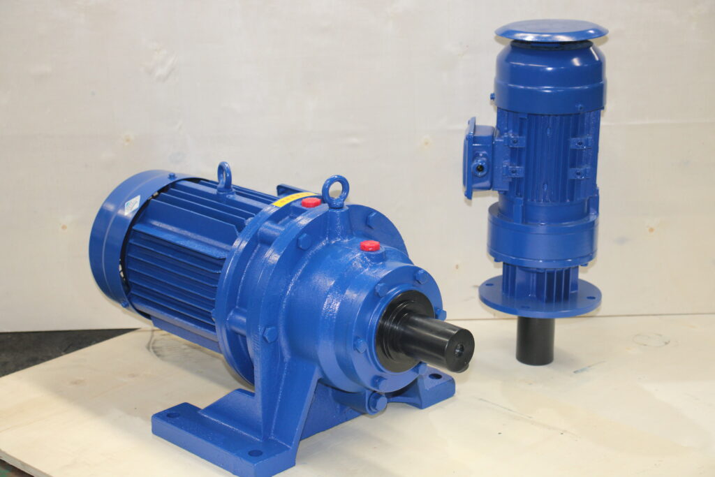
The entire transmission device of a planetary cycloidal pinwheel reducer can be divided into three parts: the input part, the reduction part, and the output part. A double eccentric sleeve offset by 180° is mounted on the input shaft. Two roller bearings called rotating arms are mounted on the eccentric sleeve, forming an H mechanism. The central holes of the two cycloidal wheels serve as the raceways for the rotating arm bearings on the eccentric sleeve. The cycloidal wheels mesh with a set of pin teeth arranged in a ring on the pin gear, thereby forming an internal meshing reduction mechanism with a tooth difference of one tooth. (In order to reduce friction, in reducers with small speed ratios, the pin teeth are fitted with pin tooth sleeves.) When the input shaft drives the eccentric sleeve to rotate one full revolution, due to the characteristics of the tooth profile curve on the cycloidal wheel and the constraint imposed by the pin teeth on the pin gear, the motion of the cycloidal wheel becomes a planar motion involving both revolution and rotation. When the input shaft rotates forward one revolution, the eccentric sleeve also rotates one revolution, and the cycloidal wheel rotates in the opposite direction by one tooth, thereby achieving speed reduction. Then, by means of an output mechanism, the low-speed rotational motion of the cycloidal wheel is transmitted through pin shafts to the output shaft, thereby obtaining a lower output speed.